Since the design did not include detailed construction methods, we had to establish a construction sequence during the planning phase. The model provided by JARC was the critical first step in making that possible.Chad Koglin, Senior Project Manager with Blaze Construction
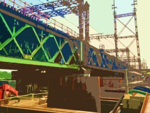
Placing the thrust block concrete was one of the many challenges of constructing the siphons at the Gordie Howe International Bridge Michigan Interchange. Together, Blaze Contracting Inc. (Blaze) and J.A.Roberts Co. (JARC) used a 3D model to establish a constructible sequence that separated the pour into multiple lifts.
Large thrust block poses challenges
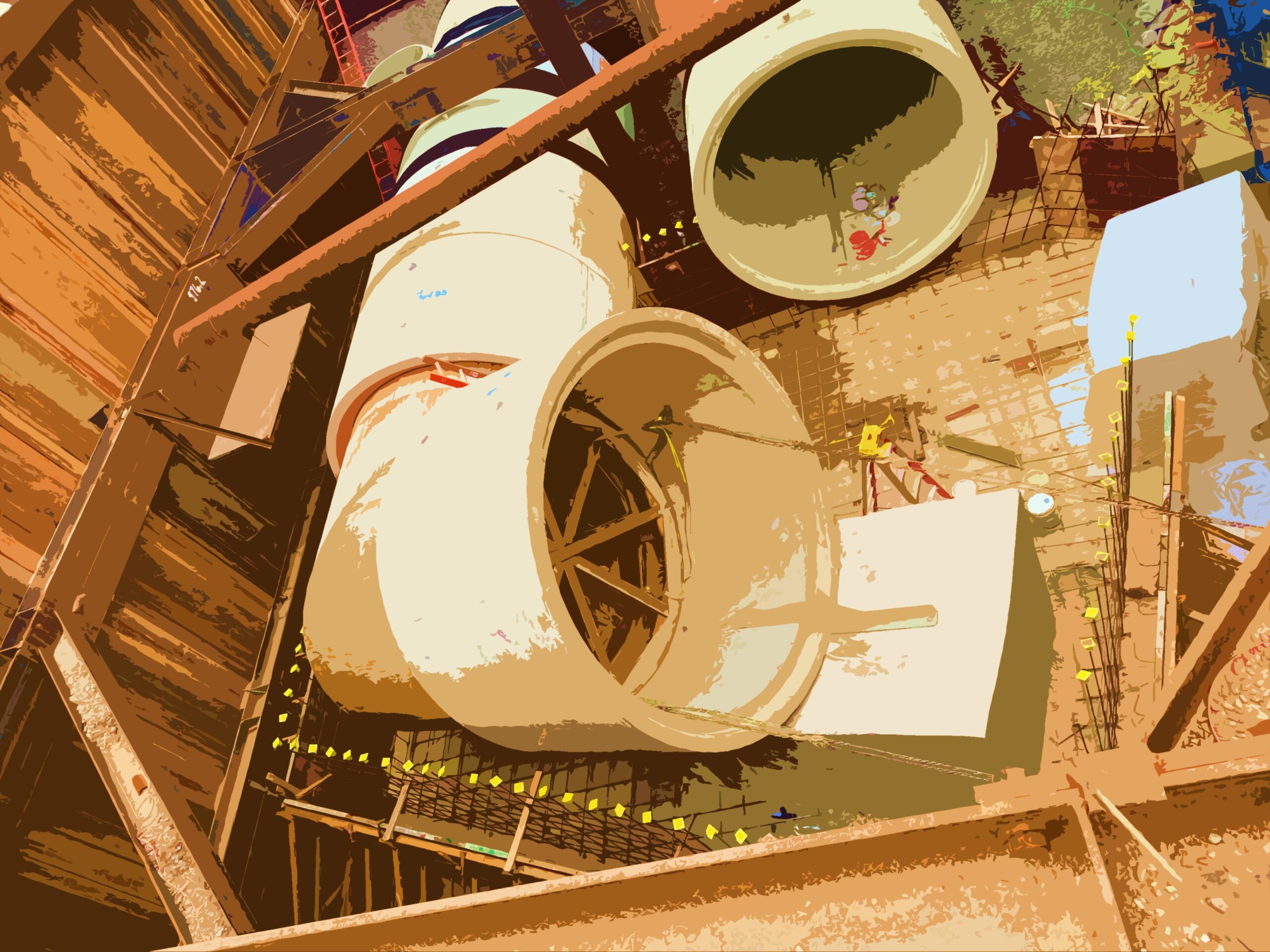
Two parallel runs of 144” diameter reinforced concrete pipe (RCP) had a compound bend. Entering the bend, the RCP was mostly level. The change in alignment of the RCP at the bend consisted of a 70-degree deflection angle in the horizontal plane and a 19-degree deflection angle in the vertical plane. The compound bend needed to be encased in a massive thrust block that was 23’-5” feet tall.
Not only was the thrust block large, but it needed to be built in conjunction with setting RCP and backfilling. The design detailed the full thrust block dimensions, but no details were provided for constructability. The contractor was allowed to pour the thrust block using multiple lifts, but they had to determine the limits of each.
Establishing a construction sequence
Blaze engaged JARC to help establish a constructible sequence for the thrust block, and together, they determined the best starting point was to model the final geometry. From there, each feature was analyzed with respect to sequence and constructability. Prior to working on this scope, JARC provided Field Shop Drawings for the RCP layout that established the work points of the RCP runs, and length and orientation of each section of RCP. Using a 3D model, JARC implemented the following high-level approach to establish a constructable sequence.
1. Modeled the full thrust block per the dimensions in the design plans.
2. Modeled the RCP to fully reflect the layout as per the Field Shop Drawings.
3. Modeled the wood elbow that was used to bridge the gap between horizontal and inclined runs at the compound bend.
4. Determined which RCP sections were fully or partially within the thrust block, meaning they needed to be in place prior to the pour. The inside run had one horizontal section and one inclined section within the block. The outside run had two horizontal and two inclined sections within the block.
5. Established the top of mud mat as the bottom of the thrust block.
6. Detailed cradles to support the RCP on both the horizontal and inclined runs. The cradles supported the difference in elevation between the top of the mud mat and underside of the RCP in its final position.
7. Established the top of the first lift as an elevation that was slightly lower (~8”) than the lowest point on the first inclined section of RCP. This allowed the pour to be made without any inclined RCP in place.
8. Established the top of the second lift as the elevation that locked in the first inclined RCP sections and was slightly lower (~2”) than the lowest point on the second inclined RCP section at the outside run.
9. Established that the remaining concrete was then poured as a final lift.

Upon finalization of the construction sequence, JARC provided Blaze with Field Shop Drawings that included cradle dimensions with reinforcement details, showed the sequence of construction, and detailed each thrust block lift. These drawings were utilized during field planning and execution of siphon and thrust block construction.
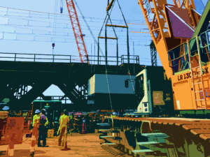
Thrust block built on schedule
Blaze was required to meet strict schedule deadlines for the siphon construction. The effort put forth by Blaze and their subcontractors to plan and coordinate the operations allowed the work to be completed on time.
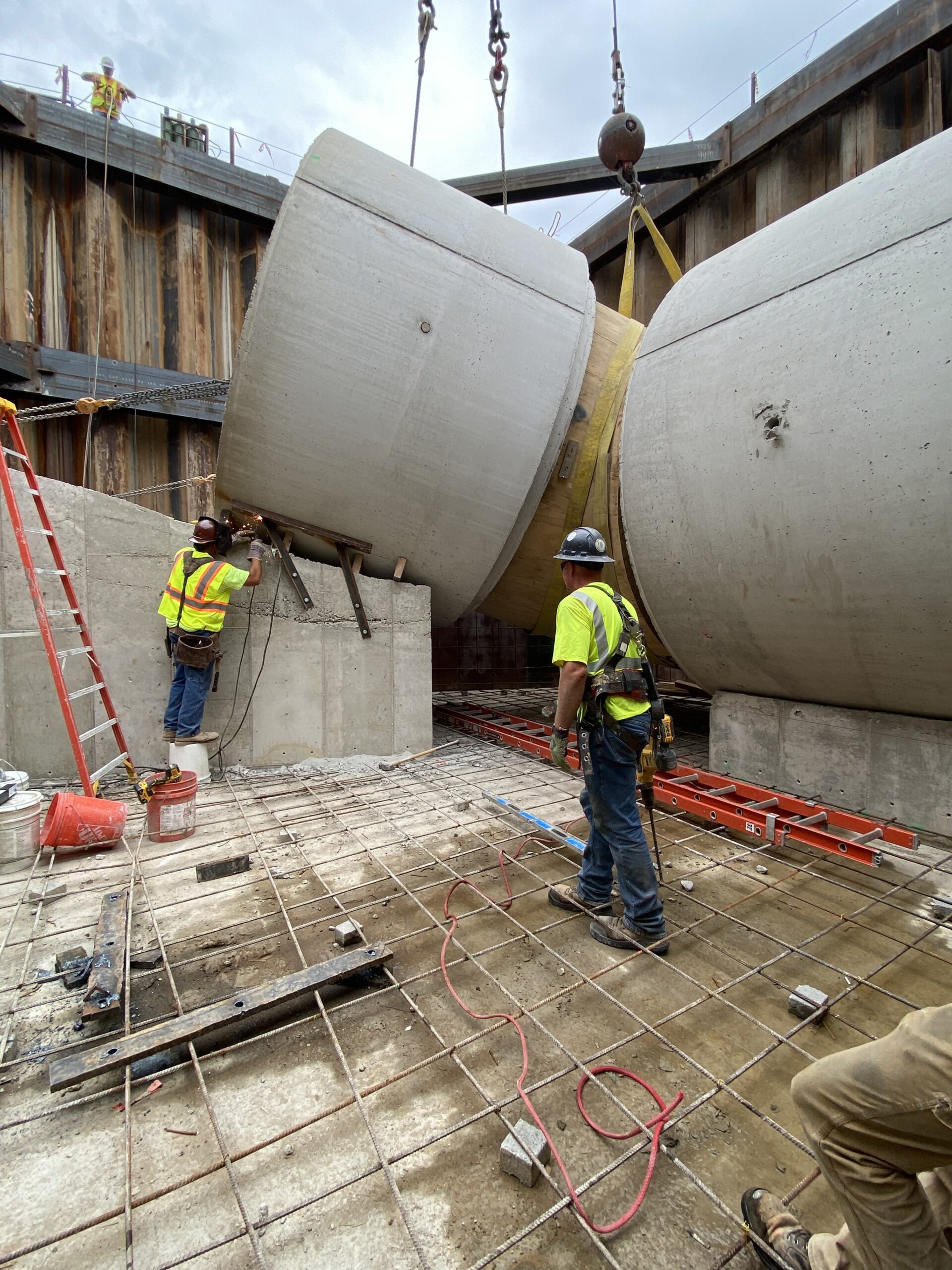
Photo Credit: Chad Koglin
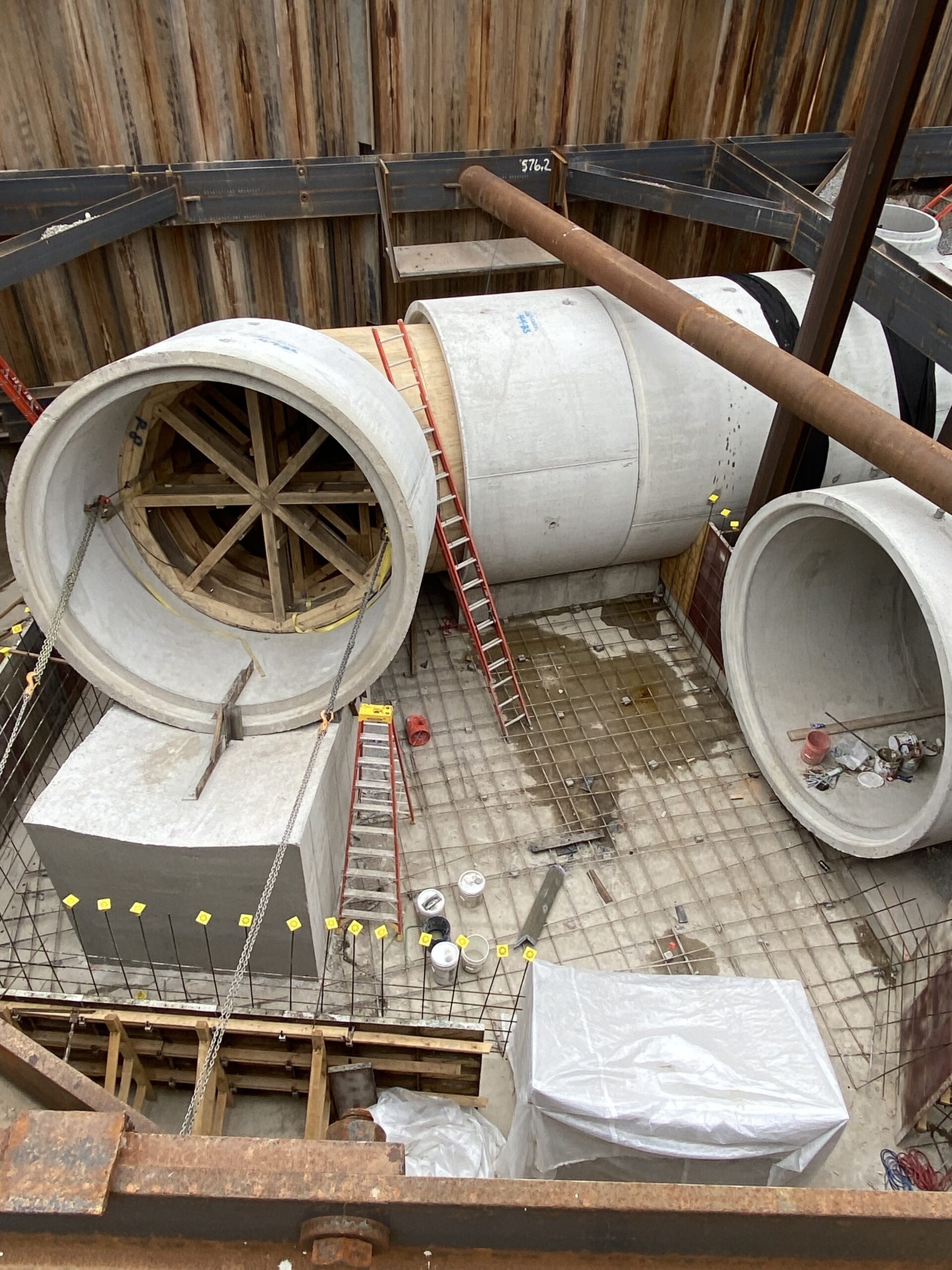
Photo Credit: Chad Koglin
Chad Koglin, Senior Project Manager at Blaze Contracting Inc., played a key role in leading the planning efforts.
“We could not have completed the thrust block construction as quickly without using the model for visualization,” Koglin said. “It allowed us to pull dimensions and elevations as needed. Since the design did not include detailed construction methods, we had to establish a construction sequence during the planning phase. The model provided by JARC was the critical first step in making that possible.”
Learn more about Blaze Contracting Inc. at their website https://www.blazecontracting.com/